Wullenweber/CDDA Antenna Homepage Like the rhombic antenna, the Wullenweber is a bit of an "orphan" antenna in the sense that it is so large to be impractical for anyone other than government intelligence agencies and the military. The Wullenweber antenna is also a receive-only antenna intended for DF and signal intercept. Also like the rhombic, the Wullenweber is the darling of the military as far as antennas for this application are concerned. 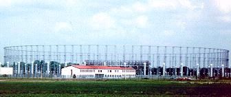 The Wullenweber is more technically known as a CDDA or Circularly Disposed Dipole Array and synonymously also as the CDAA or Circular Dipole Antenna Array. The Wullenweber is more technically known as a CDDA or Circularly Disposed Dipole Array and synonymously also as the CDAA or Circular Dipole Antenna Array. Wullenweber antennas are best known by their military designations. The AN/FRD-10 is a Navy two vertically polarized band version and is most commonly encountered. The AN/FRD-10 low band is from 2-8 Mhz (2 octaves of frequency coverage) and has 40 elements in a circle. The AN/FRD-10 high band operates with 120 elements outside of the low band circle. The AN/FLR-9 is the Army and Air Force version with three bands, two lower vertically polarized bands and one upper horizontally polarized band. The AX-16 (also known as the "Pusher") is a 2 band miniaturized version of the AN/FRD-10 antenna and is used mostly in Britain where space is a premium. The diameter of the outer ring of elements is only about 400 feet, roughly half the diameter of the Pusher's larger cousins. These antennas are truely majestic and have been dubbed various descriptive names by local inhabitants of nearby civilian communities. Names such as the Dinosaur Cage, Elephant Cage or the Turkey Cage are common. Most sit on sites of around forty acres and have a two story 40 meter square cement operations building in the center of four concentric circles of poles with a diameter of almost a thousand feet. Poles measure from eight feet to over a hundred feet in height. Security is always tight at these facilities because they are always involved in intelligence gathering operations or electronic spying. The location of each station geographically is usually purposeful relative to the intended spying target(s). Nominal operational range is usually around 3200 miles on HF frequencies, the antennas are omnidirectional and the Wullenweber is commonly optimized for arriving wave angles of 10-30 degrees or 45-60 degrees. 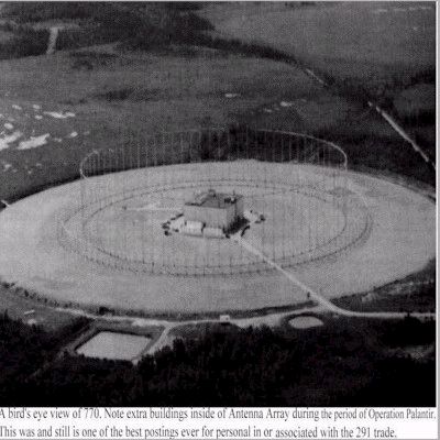 As mentioned above, the AN/FRD-10 is most common. It covers two bands and the overall diameter of the largest of the two concentric rings is 850 feet and the smaller (low band) ring is around 750 feet diameter. The high band antenna elements are on the outside and the low band are on the inside. Inside of the low band (inner) circle is the low band screen, nothing more than hard copper wires running up about 90 feet on 80 wooden poles down to a circular copper ground bus bar. This screen operates to screen the low band elements from backscatter and signals arriving from a direction other than that desired (after all the CDDA is a DF antenna). There are 40 low band elements folded dipoles that are about 120 feet high. The high band elements are sleeve monopoles and are up about 80 feet. There is generally one high band element for each three degrees of azimuth. Between the outer high band circle and the inner low band circle is the high band reflector screen that functions the same as the low band screen. From outside to inside the order of the circles is as follows: high band sleeve monopoles, high band reflector screen, low band folded dipoles and at the center: low band screen. The entire antenna site sits atop a ground screen that is 1300 feet diameter. Each element is fed by large 75 ohm very low loss coax which is meticulously phase matched across the antenna array before it enters the concrete ops building at the center of the array. The cables then enter a series of primary multicouplers that function to distribute the RF energy from each element. One tap of the low band multicoupers goes to a goniometer which switches the elements electronically and provides a "chopped" version of the RF which is then used in either sum or difference modes to give azimuth information. There is a separate goniometer for the high band array. The other outputs of the multicoupler will go to secondary multicouplers and actually enters the receivers. The real unique use of the CDAA antenna is that certain elements can be selectively chosen and electronically added or subtracted in phase effectively synthesizing an array that behaves as if the elements were a linear end-fire array with substantial gain. This permits the construction of electonic "sector" beams that are 30 degrees wide or "monitor" beams that are 15 degrees wide. The array can also be set up to give a truely omnidirectional pattern. The AN/FLR-9 used by the Army and Air Force has a third band of elevated dipoles that,while allowing broader frequency coverage, creates problems with the omnidirectional pattern on the third horizontally polarized band because the horizontal polarization makes things substantially more tricky. The AN/FRD-10 is termed an "outward" looking array because the high band elements are on the outside of the antenna. Other designs are the opposite with the high band inside the low band and use the low band as a high band screen. This is termed the "inward" looking mode. The average FLR-9 antenna is said to cost around 15-25 million US dollars to construct 
The FRD-10 is actually the Navy version of the Wullenweber and is also known as CLASSIC BULLSEYE. The data here might give you a start to figuring out the electrical operating theory of the Wullenweber however critical details are not in the public sector. You may have some trouble building this antenna as the US Government describes costs of between $800,000 and $900,000! Details of the antenna curtain itself is readily available in the public domain. The finer details of the phasing and goniometer circuitry is presumed to be classified
as secret. I however think one might be able to make a sector version of the Wullenweber
with a reasonable cost associated. Perhaps an arc of 60 degrees with 20 monopoles and
the reflector curtain for high band only with the associated ground screen. That would be
interesting to mess around with. I'm just not sure about phasing and the goniometer part!
The FRD-10 is constructed in two design formats with different dimensions. The original was at Hanza Okinawa and modifications to the design resulted in subsequent differences. These changes were in the diameter of the circles, number of antenna elements, spacing and heights.
The feedlines involved are obviously a big deal here and the feedlines arrive at the central building from 4 sectors (90 degree arcs). These feedlines arrive from both the low band and high band elements.
The low band antenna consists of 40 folded monopole antennas each at very 9 degrees of azimuth. These monopoles atop a base insulator with nonconductive guy wires. There is an aluminum 32 inch crossmember at the top to suspend two parallel aluminum wires adjacent to the mast monopole. The mast is an estimated 60 feet high and about 5 inches diameter. There is a large ceramic insulator at the base. The wires hang off the aluminum cross bar and at their base are resistors to the ground curtain. The mast is fed with a 75/250 ohm transformer and the whole affair ends up being a folded monopole. The feedline is RG-85 A/U.
The low band reflector screen is made up of 80 screen panels (some use 40) located 30 feet or so behind the monopoles. The wires making up the screen are spaced around 1.5 degrees of arc apart resulting in 700 or so vertical wires. They are suspened with 90 foot lengths with insulators at the top and connection to the ground screen at the bottom. They are tensioned and supported by 100 foot wooden poles. Wooden booms span each pair of poles from which the reflectors (and insulators at the top) are suspended.
The high band antenna consists of 120 sleeve monopole antenna elements located at 3 degree intervals of azimuth with a circle circumfrence of 440 feet or so. The monopoles are 25 feet tall and are not guyed. The top monopole is 6 inches diameter and 17 feet or so long. This top section is inserted at it's base inside the bottom section which is 16 inches diameter and roughly 8 feet long. with an overlap of the top section inside the bottom of around 25 inches making a capacitor of sorts. Inside the top section's base is a 25 inch rod with at the top section a shorting disc. The bottom of this rod is the monopole feedpoint. The lower 16 inch section is grounded to the ground screen.
The high band reflector screen is made up of 120 screen panels located around 12 feet behind the monopole circle with a screen circle circumfrence of around 420 feet. The construction is similar to the high band screen. There are around 2,000 wires and each screen is spaced around 11 degree intervals. Each wire is around 25 feet long. Support poles are around 30 feet tall.
Underneath this whole affair is the reflective ground plane. There is a large ring of ground plane made from copper mesh measuring 350 feet at the inner diameter and 500 feet at the outer diameter. Outside this ring are radially disposed ground radials each spaced 1 degree of arc apart extgending from 500 feet out to 650 feet. At the base of each monopole is a copper grounding sheet 8 feet in diameter. Needless to say this antenna has an excellent ground system!
Feedlines are buried en route to the shack and electrical lengths must be carefully controlled and equal. Tolerances less than an inch are important.
The overall principal of this antenna is that the advancing wave front will encounter one monopole first the the two on each side, subsequently the next pair outward and on and on. The feedlines are combined using phasing lines or delay lines that delay the arriving signal such that each monopole output arrives at the receiver simultaneously at the receiver. In effect a circular array is made to perform as if it were a linear one. The reflector screen provides a unidirectional pattern for each monopole with significant gain even before summation using the delay phase lines. The goniometer permits the user to in effect electrically steer the phasing/delay lines by selecting a given arc of monopoles upon demand. The resulting pattern is very narrow and the gain very high. The actual antenna feedlines are capacitively coupled to the goniometer/phasing lines but the details of all of this are obscure.
The low band monopoles use the folded monopole design to create an electrical mirror image dipole element in the ground screen. This makes the size necessary for the monopole around half of what it would otherwise be (over 150 feet for a full sized half wave dipole in the middle of the design frequency). The large diameter mast gives high Q. The wire elements futher augment this electrically. Height is between one eighth wave lengths at 2 mhz and about a half wave a 9 mhz. Impedance is between 10 and 30 ohms.
The high band monopoles also achieves the high Q goal and also uses the mirror image to create a dipole electrically. Similar impedance is likely.
This is all I could glean related to actual construction details. The dimensions are not likely to be exact. Monopole designs are derived from surplus monopole antennas described by others. Scales are from photographs.
The Wullenweber's days may be numbered. It shines in allowing the listener to electronically steer the beam and change the pattern shape at will. Modern DSP methods can do much of this now using multiple receivers and there are other more fancy ways to do wavefront analysis. Lastly, we can only guess at the contribution of space-based satellite technology (i.e. listening from only 400 miles away with line of sight in low earth orbit as opposed to from thousands of miles away through atmospheric reflections). Numerous Wullenweber intelligence gathering stations existed in the Cold War era, many having begun for the same purpose during World War II. While I don't have a comprehensive listing (and many have been decommissioned), I know of the following CDAA station; Fort Devens, MA (I know of this because it is not far away. Field Station Ausberg closed in 1993 having begun ops in 1970. It employed 1800 people with Army, Navy and Air Force units monitoring East Germany, Poland, Czechoslovakia, Hungary and all of Western USSR. San Vito dei Normanni Air Station, Italy opened in 1960 and closed in 1993, employing 700 Air Force and fewer Navy intelligence personnel listening to the same areas as Field Station Augsberg along with additional listing in the Middle East. RAF Chicksands, UK opened in 1950 with US personnel also listening to the East Block nations and the USSR with specific responsability for monitoring the Soviet Air Defense Network. Chicksands ceased Allied operations in 1995. Clark AFB in the Phillippines used an AN/FLR-9 to monitor Chinese and Vietnamese communications and was closed after the Mount Pinatubo eruption. Canada is home to a number of Wullenweber stations. CFS Masset is on the North coast of Graham Island in British Colombia. The Masset station is believed to listen to the Russian naval base at Petropavlovsk and to the Russian Pacific surface and submarine fleet HQ in Vladivostok. The snow covered image here is a CDAA antenna at Elmendorf AFB in Anchorage.  Build your own CDDA Wullenwebber Anyone with further information related to the Wullenweber antenna, please forward it to me or email me below. The information on this page is entirely from public domain sources and the intent is purely technical and related to this fine example of RF engineering. Thank-you.
2021: You can still see a Wullenweber at the USASA Field Station, Augsburg, coordinates: 48.4512N, 10.8627E. Here's a photo from Google Maps:
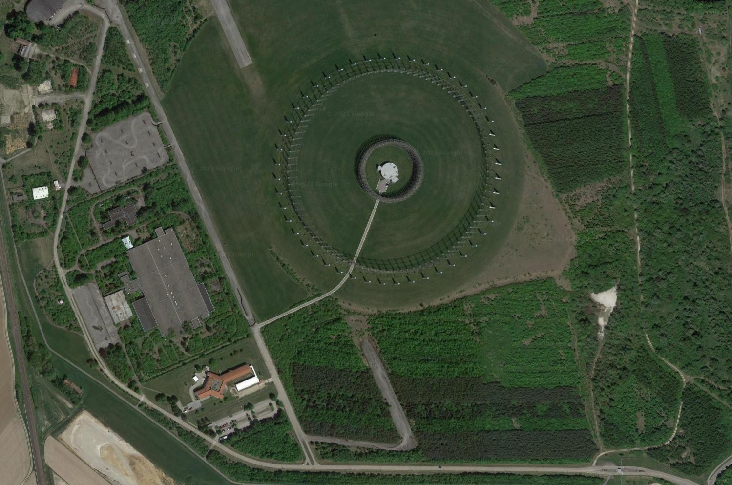
Wikipedia says: United States Army Security Agency (USASA) Field Station Augsburg was the site of a Wullenweber AN/FLR-9 (V8) radio direction finder, established during the Cold War. Field Station Augsburg was located on Gablingen Kaserne, near the village of Gablingen just north of Augsburg in Bavaria, West Germany. It was one of nearly 20 field stations positioned strategically around the world by the U.S. Armed Forces during the Cold War. Field Station Augsburg opened in 1970[1] and closed in 1998, at which time it was turned over to the German government.
The Station was owned and managed by the National Security Agency and staffed by the U.S. Army Security Agency (USASA), which later became U.S. Army Intelligence and Security Command, in conjunction with other branches of the U.S. Military and various allied forces. Personnel assigned to Field Station Augsburg were composed of individuals who scored high enough on the Army entrance exams to be classified as "ST" or a skilled technician, which is the Army's top-ranked job category. The Station was staffed 24 hours a day,
by means of rotating shifts.[1]
There was a saying in the 1970s that if the intelligence units were able to effectively do their job, the combat units wouldn't have to do theirs. The Station's mission was to monitor the communications of Cold War enemy nations, their allies, and client states around the world. The information gathered was time-sensitive and, based on its importance and classification, that information was collected, analyzed and passed through intelligence channels on a "real-time" basis. Personnel assigned to the 1st, 2nd, and 3rd Operations Battalions and the Support (Service and Maintenance) Battalion, and the successor
Military Intelligence (MI) units (701st Military Intelligence Brigade - 711th, 712th, 713th, & 714th MI Battalions) at Field Station Augsburg served as Morse and non-Morse Cryptologists, Voice Intercept,
and Radio Direction-Finding Operators, as well as Traffic Analysts, Equipment Repair and Cryptanalysis/Cryptanalytic Technicians.
A Company of the 204th Military Intelligence Battalion was assigned to nearby Augsburg in 1991 until U.S. operations at the station ultimately ceased in 1998.
With the end of the Cold War, Field Station Augsburg lost much of its strategic value. It is currently reputedly used by the Bundesnachrichtendienst. The Wullenweber / Flair-9 antenna is still in place as of late 2020.
Extra notes by EI8IC: Since posting this page, I have received a KMZ file of all CDAA antenna sites from Ed. This file can be downloaded and displayed on Google Earth. Ed writes: The KMZ file has folders which link to the old Soviet Wullenwebber's (KRUG) constructed in the Soviet Union, as well as another folder (Other countries) which lists the Soviet KRUG constructed in Cuba. There are other folders relating to other Soviet type CDAA's (dubbed THICK EIGHT, and FIX24). In additiona, there is a folder with the location of all the Navy FRD10's, the Army/Air Force FLR-9, the
Plessey Pusher (US equivalent was the FRD13, and several Federal Communication Commission Monitoring sites where a CDAA (nomenclature unknown at present) was installed. The people who helped compile this file (Google Earth contributors), spent quite a bit of time to ensure the accuracy of the information in the file. I have several hundred Freedom of Information Act documents which were used to compile this file and make it as accurate as possible. There is another CDAA Sites collection file on Google Earth, but more than half the files are bogus, and have never been verified.
Why are Wullenweber CDAAs obsolete? - That link opens an interesting discussion with plenty of onward links that chats about why the Wullenweber circularly-disposed antenna arrays (CDAAs) have nearly all have been demolished.
The Last Elephant Cage - Here's a great video that documents the history of the FLR-9 antenna located in Anchorage, Alaska and its 50 years of service to the NSA mission.
MAINTENANCE MANUAL FOR ANTENNA GROUP COUNTER MEASURES RECEIVING SETAN/FLR-9(V7)/(V8) - Here's a manual for construction and operation.
Wullenweber Notes - other interesting notes.
|