Rhombic Antenna Design The primary requisite of a beam-type antenna for good reception is a high signal-to-noise ratio. For good transmission characteristics at the frequencies at which rhombics are employed, a relatively low vertical angle of radiation (0 to 20 degrees) and controlled lobing of the radiation pattern in the horizontal plane are required. The full rhombic antenna meets these requirements and, in addition, has a broad operating frequency range. The full-rhombic antenna can be considered as a development of the half-rhombic or inverted "V". However, the rhombic types to be discussed are designed for operation in the horizontal plane. By placing two half-rhombics side by side and terminating their ends with a noninductive resistance, a unidirectional lobing pattern is obtained in the direction of the terminated end. The tilt angle is half the included side angle and must equal 90 minus half the feed point angle. In order to obtain the correct phasing of the lobes for maximum radiation in the desired direction, the straight line distance A-B, between the centers of the legs, must be one half wave length less than the distance A-B-C (from each leg center along the wire itself, where A-B is the shortest distance). This follows from the fact that lobe 1 is 180 degrees out of phase with lobe 3. By making the distance between the lobes one half wave length (180 degrees) less, lobe 1 will arrive at point B in correct time phase to add to the field of lobe 3, and thus increase the intensity of radiation in the desired direction. A similar action takes place between lobes 2 and 4 on the other side of the rhombic. All other lobes combine to produce a cancellation of radiation energy in the line of the minor axis C-D. Correct termination of the rhombic antenna with approximately an 800 ohn nonreactive resistance produces an almost infinite front-to-back ratio. This means that very little radiation takes place toward the input end of the antenna. The gain of a rhombic with side lengths of four to five wavelengths is over 40 times that of a half wave dipole. About one half of this gain is realized by using two wave lengths to each of the four sides. The important items in the design of a rhombic antenna are as follows: 1. Vertical wave angle. 2. Electrical length of the sides. 3. Tilt angle. 4. Height of antenna curtain above the ground. The starting point in the design of a rhombic antenna is the determination of the required vertical wave angle of propogation, which depends primarily on the distance to be covered and the frequencies to be used. The distance coverage ranges from 200 miles to over 3,000 miles, while the practical frequency range is from 5 megacycles to 35 megacycles. Maximum distance coverage is obtained with wave angles from 0 to 10 degrees (the vertical wave angle is computed in the same manner for other long single wire antennas). Once the correct wave angle has been selected, the side length L, the tilt angle theta and the height above the ground H, must all be determined. Since the wave angle becomes smaller as the side lengths of the rhombic are increased, it can be expected that, as the frequency of the transmitted signal is increased, the wave angle of propogation is decreased, with a consequent gain in distance coverage. If a particular rhombic whose lowest operating frequency is 5 megacycles has a 2-to-1 frequency coverage, it will give good directive radiation up to 2 x 5 megacycles or 10 megacycle. In order to communicate with a station located 400 miles away, it was found that when using a 5 megacycle signal the approximate wave angle was 48 degrees via the F1 layer(200 mile height). When the frequency was raised to 10 megacycles, the distance with the same antenna was increased to approximately 900 mile and the wave angle was reduced to approximately 22 degrees. Varying the height of an antenna modifies the radiation patterns in both the vertical and horizontal planes, and also affect the over-all gain, particularly if the rhombic has short length sides (2 wave lengths per side, or less). In order to eliminate the complex mathematics necessary to determine optimum rhombic dimensions and height above ground; the two design charts are included here. The first chart is used to design a rhombic antenna for maximum output radiation in the desired direction. If any one of the four quantities: the height, length, angle of tilt or wave angle, is known; then the other three quantities can be found in this chart. 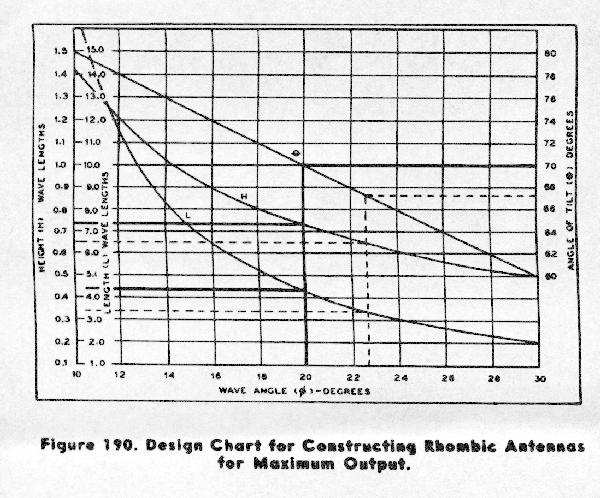
Example use of maximum output chart: in order to determine dimensions for a 12 megacycle rhombic with maximum output at 20 degrees wave angle, locate the value 20 degrees on the wave-angle scale at the bottom of the chart, then draw a straight line from that point through the curves of the chart (the line is perpendicular to the wave-angle axis). The line will cross the three curves on the chart. At each point where this line intersects the three respective curves, draw a horizontal line from the curve intersection to the respective axis. These lines are drawn on the maximum output chart to illustrate appropriate use of this design method. The values obtained are as follows: Height (H): 0.73 wave lengths (by conversion 60 feet). Length (L): 4.25 wave lengths (by conversion 388.5 feet). Angle of tilt (theta): 70 degrees. The results of the use of the design chart yields the same results as a more complex mathematical derivation and is much simpler. To further illustrate the use of this chart, the following example is given. Suppose that for a given installation, the height of the antenna is to be 0.65 wave length. Find the leg length (L), the tilt angle (theta), and the wave angle that results. To solve this problem by means of the chart, proceed as follows: Draw a vertical line through the point on the H-curve which intersects a horizontal line corresponding to 0.65 wave length from the height (H) scale. Draw horizontal lines from the points of intersection of the vertical ine on the curves to their corresponding scales. All of these lines are shown as dashed lines on the maximum output chart. Then read the values on the scales. They are as follows: Length 3.4 wave lengths, tilt angle 67.3 degrees and the wave angle is 22.7 degrees. The rhombic antenna design methods discussed are based on an ideal system for maximum transmission and reception efficiency under average conditions. For various reasons, a departure from the ideal design must be made. For instance, where space considerations are a factor, the side lengths of the rhombic may have to be shortened. On the other hand, the installation may not have sufficient height due to unavailability of supporting structures of either wood or metal construction. The length of the sides of the rhombic may also be limited because of tactical reasons. Sometimes the antenna sides are deliberately made shorter to increase the vertical wave angle of propagation at higher operating frequencies, and to broaden the radiation pattern. The latter is usually necessary to offset ionospheric effects, which may cause a shifting of the communications path in long-distance communication. Regardless of the reasons for a compromise in the design, for optimum performance in a given frequency range, two basic factors must be considered. First, if the desired height cannot be attained, the length of the sides must be increased. Second, if the side lengths are shortened, the height of the antenna must be increased. In either case, the over-all efficiency of the rhombic is lowered. The term efficiency here refers to the signal gain and directivity for transmission in the forward direction and signal-to-noise ratio for reception in the same direction. 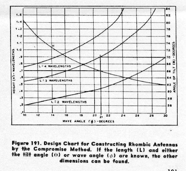
One significant difference in the maximum-output design method and the compromise-design method may be observed by comparing the maximum output and compromise design charts. Note that the tilt angle and wave angle in the compromise design chart are not complements of each other. This is because, the usual relationship where the sin of the tilt angle is equal to the Cosin of the wave angle no longer is practical in the calculations. Since the wave angle is affected more by length than by height, the formula used to calculate the tilt angle for a given height is: sin (tilt angle) = L-0.371/L Cos (wave angle) The compromise chart is used in the same manner as the maximum output design chart except that the leg length (L) and one other value now must be known. For example, suppose that for a given antenna it is known that the leg length (L) is 3 wave lengths and that the desired wave angle is 21 degrees. Find the correct height (H) and tilt angle (theta). To solve this problem by means of the compromise-design chart, proceed as follows: Draw a vertical line from the point 21 degrees on the wavelength scale through the curve L=3 wave lengths. Then locate the points of intersection with curve H and extend a horizontal line to the height (H) scale. Locate the point of intersection of the vertical line with the curve L=3 wavelengths and extend a horizontal line to the angle of tilt (theta) scale. These horizontal lines indicate that the correct height is 0.7 wave lengths and that the correct tilt angle is 70 degrees. 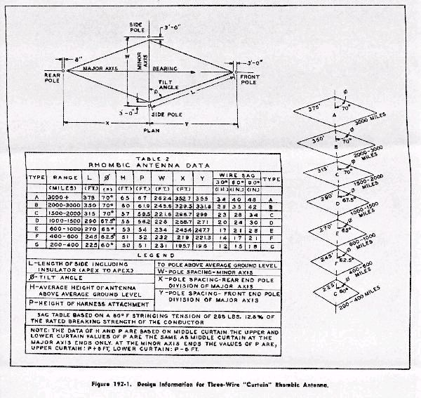
Termination Impedance The primary purpose of the terminating impedance of the rhombic antenna is to produces a sharp, unidirectional radiation pattern. For low-power (up to 1 KW) transmission, the termination impedance is usually an 800 ohm noninductive carbon resistor. For reception, the terminating impedance is generally composed of low-wattage carbon resistors. The transmitting rhombic is usually terminated with two to four specially designed carbon resistors of about 200 watts rating. The resistors are sometimes mounted in a spring-clip fuse mounting, the whole assembly being housed in a weather-proofed plywood box about 2' X 1.5 X 1'. The box is located at the terminated end of the antenna on the pole. In order to minimize capacity effects, the resistor combination is connected to form a series circuit. The connecting leads in the terminating network must be made as short as possible to prevent inductive effects. If insulators and supporting elements with metallic fittings are used throughout the antenna, it may be necessary to tune out the resulting lumped capacitances by critical adjustment of the connecting conductors in the terminating network. These lumped capacitances produce undesirable resonance effects at certain frequencies, which in turn modify the unidirectional pattern otherwise obtained with proper termination. If it is desired to make frequent adjustment of the termination, the impedance housing can be placed at a suitable height near the base of the terminating pole. The terminating impedance network is then connected to the antenna termination with an 800 ohm line. The latter may consist of nichrome or stainless steel wire (sometimes a bank of carbon filament lamps connected in series-parallel can be used for the termination. 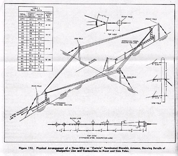
It has been found in practice that when the conventional rhombic is operated over a wide frequency range, the input impedance varies considerably (theoretically the input and output impedance should be equal, although the latter usually has a slightly higher value). For example: the input impedance of a typical single-wire rhombic varies from a maximum of about 820 ohms to a minimum of 700 ohms, when the applied frequency is varied from 5 megacycles to 13 megacycles. Increasing the frequency up to 22 megacycles reduces the input impedance to a minimum value of 600 ohms. Thus it can be seen that even with a proper 800 ohm termination, resonance effects with a departure from the ideal unidirectional lobing cannot be avoided, using the single-wire rhombic. The problem of maintaining a constant impedance with respect to the terminating impedance over a wide frequency range, can be solved by the use of a multiple-wire rhombic, commonly called a "curtain" rhombic, as shown in the figure. The spacing of the wires at the side poles, in the vertical plane, is 1 to 5 feet. When the frequency is varied from 5 to 21 megacycles, the input impedances remain fairly constant, with a maximum variation of plus or minus 50 ohms. A 600 ohm feedline can be coupled directly to the input of the multiple-wire rhombic. Dissipation Line When rhombic antennas are operated at high power (above 1 kw), the problem of input impedance termination becomes more complex. In the half-rhombic antenna, for example, about 50 percent of the r-f power is dissipated in the terminating impedance. Compact, non-inductive resistors capable of dissipating over 1 kw of power have, to date, been impossible to manufacture. It has been found practical to use a dissipation line consisting of a suitable length of stainless-steel wire, as a terminating impedance for powers between 1 kw and 40 kw. Steel wire with a galvanized surface can also be used, but it will change value in time, due to rusting at points where the galvanized coating breaks open. 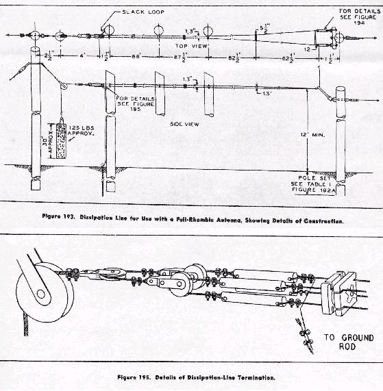
The dissipation line is constructed of No. 14 A.W.G. annealed, stainless-steel wire, and includes the down lead, all in one length. The down-lead portion is made up of 2-wire line (each wire consisting of 2 strands No. 14 A.W.G. stainless steel, long-lay twist), spaced 12 inches, and has a characteristic impedance of approximately 650 ohms. The down-lead becomes part of the horizontal portion of the dissipation line by a right-angle bend, and at this point a modified exponential line begins. The 2-wire down lead is transformed into a 4-wire dissipation line without the necessity of joining or splicing. The 12 inch spacing diminishes, the 2 strands (long-lay twist) of each line wire become separate spaced lines, and thus, in a line length of exactly 62.5 feet, the 12-inch spacing tapers to 5.5 inches as the side members diverge to 1.3 inches at the dissipation-line spreader insulator. In the next 62.5 foot length of line, the 5.5 inch spacing tapers to 1.3 inches, while the side members remain spaced 1.3 inches apart. From this point, the line continues as a 1.3 inch square, spaced, 4-wire line. The modified exponential portion of the dissipation line transforms the approximately 650-ohm impedance of the down leads to approximately 200 ohms. The equally spaced 4-wire portion of the dissipation line is fundamentally two 400-ohm lines in parallel, one which is terminated in an open circuit (not connected to anything) and the other of which is terminated in a short circuit (ends connected diagonally) and grounded. 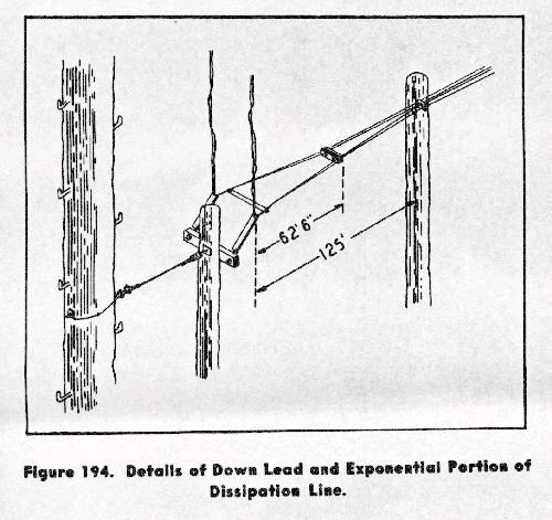
The nichrome-wire, or stainless-steel-wire dissipation line is usually grounded at the electrical center as a precaution against lightening hazards. An alternate impedance-termination system, generally used for input powers above 50 kw, is the re-entrant line termination. In this system, the rhombic is terminated in a transmission line, which in turn is coupled back to the input through the proper voltage-matching and phasing networks. Thus, some of the energy in the dissipation line is fed back to the antenna, so that considerably less than 50 percent of the energy is wasted. The energy in the re-entrant line is fed back to the antenna input line in the proper phase by means of a matching-stub arrangement. If quarter wave stubs are used, the center point of the stub shorting element can be grounded as a protection against lightening hazards. It is obvious that for any variation from the stub frequency, the stub must be retuned.
|