Rhombic Antenna Home Page
While amateur radio operators today largely employ rotating array antennas such as the Yagi dipole array and the cubical quad antenna, some still use wire antennas, some of which can afford higher gain and lower receive noise characteristics. In fact, the rhombic antenna is usually described as the "King of antennas" because of it's very desireable characteristics. The rhombic antenna is basically a diamond-shaped wire curtain that is made of 4 wires, each several wavelengths long connected to form a "diamond" or rhombus shape . The diamond is constructed with the narrowest ends left open for the feed point on one end and a non-inductive resistive termination on the other. This creates the terminated (also called non-resonant) rhombic which is a unidirectional antenna with broad bandwidth. Non-terminated (also called resonant) rhombics do work but have narrower useful bandwidth and are bidirectional (non-resonant rhombics are fed on one end and the opposite end is left open. In my experience both non-resonant and resonant rhombics work quite well.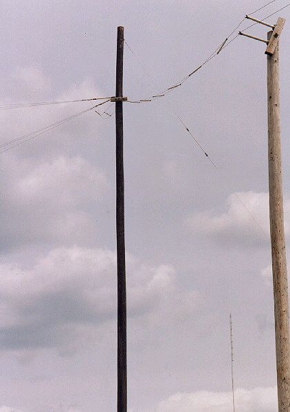 All wire antennas tend to be less "noisy" on receive and longer antennas like the rhombic are very low noise antennas with the solitary exception of precipitation static (snow and rain add small charges to the curtain and you get very high noise under such conditions). Precipitation static can be minimized by using termination resistors with a grounded center tap (leaks static to ground continuously). All wire antennas tend to be less "noisy" on receive and longer antennas like the rhombic are very low noise antennas with the solitary exception of precipitation static (snow and rain add small charges to the curtain and you get very high noise under such conditions). Precipitation static can be minimized by using termination resistors with a grounded center tap (leaks static to ground continuously).
The sides of the rhombic (with the broadest included angle) are constructed of differing dimensions to determine what radiation angle will be obtained. Half of the angle included by the rhombic side is called the "tilt angle" or theta ø and as the tilt angle is varied, the radiation angle will also vary. There exist various ways to calculate the ideal tilt angle to choose relative to the radiation angle and gain desired for a given rhombic application. Generally the tilt angle is between 65 and 75 degrees. The apex angle is the angle included by the feed point end of the rhombic and is between 30 and 50 degrees and varies with the tilt angle (the sum of half the apex angle and the tilt angle will be 90).
Height is very important for rhombics, as it is for all antennas. Basically, the radiation angle of the main beam of any antenna is related to the height above the ground and the ground characteristics. Generally, for any antenna the following height (in wavelengths)/wave angle (degrees) relationships hold: 0.5/30; 1.0/15; 1.5/8; 2.0/6; 3.0/5. As you can see, to take advantage of the rhombic's extraordinary gain for distant (low angle) communications, you will need to have the antenna at least 1.5 wavelengths high: on 14.0 Mhz, this is around 90 feet, the "usual" height used for rhombic antennas (most rhombics used are in amateur radio usually optimized for 14 Mhz or 20 meter band).
Rhombic antennas are generally fed with open feedlines of around 400 to 600 ohm impedance. This is not critical and any issues related to feeder loss and/or standing wave ratios pales in significance in relationship to this antenna's gain. In the real world things work fine without worry related to feedlines so long as you use a good antenna tuner. Use of baluns is probably unwise as this is likely to limit the useful frequency range of this intrinsically broadbanded antenna. Many commercial applications of the rhombic use what are called "exponential feeders" with the nominal impedance being 300 ohms at the feeder end and with the paired feedlines gradually spreading to a spacing of around 12 inches at the rhombic feedpoint (a distance calculated to provide the rhombic feedpoint impedance of 600-800 ohms). 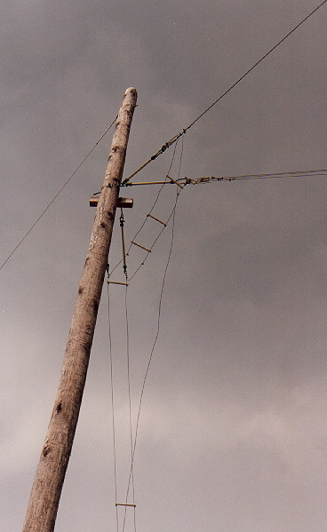 This exponential feeder provides a smooth transition of impedance and acts as a sort of impedance transformer. This exponential feeder provides a smooth transition of impedance and acts as a sort of impedance transformer.
In current antenna publications it seems very hard to find anything other than a very abbreviated discussion of rhombics and perhaps some basic design charts and dimensions for a simple rhombic. Little discussion is generally available of the more complex details important to anyone seriously interested in constructing a rhombic antenna. With this in mind, this page has some images of real-world installations and discussion of most of the important practical details you would need to be aware of to construct and maintain a proper rhombic. I am always interested in hearing from anyone with experience with building, maintaining or using rhombics. Images, plan sets and even parts from dismantled rhombics are of interest to me. I will add anything to this page that fits, and then some.
Click here for an abbreviated discussion of practical rhombic antenna design
Click here for a detailed text outlining apects of practical rhombic antenna design (under construction)
Click here to view construction images for the North American Center for Emergency Communications (NACEC) rhombic station in Minnesota
Click here to read about the World War II rhombic station in Scituate Rhode Island (Chopmist Hill)
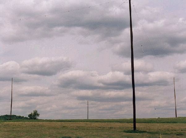
The three images included here are from the WJCR short wave station in Millersville Kentucky and the images were kindly provided courtesy of WJCR. Note the feeders are attached directly to the antenna with little concern for matching. This is not unreasonable as the loss involved is trivial compared to the gain of the antenna (I feed mine directly as well). Also note the use of three wire curtains (slight increase in gain and smoother impedance characteristics across the broad frequency coverage of the rhombic.
The issue of frequency coverage itself is also worth further discussion. While the rhombic is very broad banded, especially the non-resonant terminated antenna, in my hands when optimized for 14Mhz, the antenna is still useful from 10 through 18 Mhz. On the higher bands (18-30 Mhz), the main beam becomes unaccepably "split" with less effective gain in the resulting lobes in the azimuth plane. The antenna is still useful but limited. Perhaps the answer is to build the larger rhombics with smaller antennas that are optimized for the higher frequencies supported at a lower height from the 4 support poles. The rhombics work well when "nested" in this manner and you can conserve space in this way. Additionally, if you get really carried away, you can use the side poles as ends for other rhombics and vica versa. You can even "stack" rhombics running in different directions with clearances of anything greater than 5 feet on HF. Yes, there is a slight degradation but big rhombics are such good antennas that in the real world you shouldn't care. Designs have been built where rhombics are phased together so that in a given direction, one or more rhombics are fed in phase.
Monsterous rhombic arrays have been built in this manner and one can only guess what kind of signals resulted (it's actually rather frightening)!
Harper, of Bell Laboratories, did much of the pioneering work on the rhombic antenna and determined a famous curve that is largely used to design rhombics. Usually some optimization is needed to make sure that the main lobe and the radiation angle coincide. This usually results in a slight loss of gain because of the slightly shorter legs used for a given angle on the sides. Some additional advantage is obtained by having several wires per leg (several curtains), with up to 2 db more gain resulting.
The ability of the rhombic to provide high gain (typically over 9 db for most antennas made and often up into the 20 to 30 db area in arrays of rhombics) , narrow predictable patterns in the azimuth plane, optimized patterns for a given wave angle and physically sturdy construction make the rhombic still the choice antenna for point to point communications operations. Many large rhombic stations existed until recent times and several still are in operation.
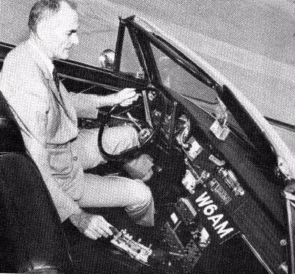
Some famous stations included WCC in Chatham Massachusetts, the Rocky Point RCA station and the Palos Verdes Press Wireless Station of the late Don Wallace W6AM's (below). These stations began as commercial stations and had many rhombics, usually with each rhombic covering a given city (again, because you can optimize the wave angle and the azimuth direction is known, you would choose a rhombic with a higher wave angle for cities that are closer and a lower angle for farther destinations). These antennas almost guaranteed an open circuit to the desired locations despite the conditions. Such arrays would usually be fed via open feeders (oftern 4 wire feed lines to limit loss over the thousands of feet of feeders) and if both directions were desired a switching array would be used to select the direction. Stations would usually have a matrix of open frame RF relays in the shack or in a switch house with a DC switch at the operator's station to select the direction desired. The feeders would arrive in the switch area in layers.
The military has used rhombic antennas for years. In fact, in World War II, the War Department had a rhombic antenna kit (TM11-2611) . This manual was designed to allow the construction of rhombics in the field with indiginous timber for supports and using tables to determine the optimum leg length and tilt angle for communications back to the United States. This design is near optimum for the largest rhombic feasible for practical HF communications.
During World War II not far from my station's location was a classified HF listening station where it is said that rhombics there were used to eavesdrop upon German submarines during the war. This station was said to be involved in the breaking of the German Enigma codes during World War II. This station was located on the top of Chopmist Hill, not far from the highest spot in Rhode Island. This location in the town of North Scituate was designed by Thomas Cave of the Federal Communication Commission's Radio Intelligence Division (RID). The RID had leased the 183 acre Stoddard Farm, chosen for it's location and open acreage that was amenable to a large wire array receiving station far from industrial and power line noise sources. Nationwide there were 150 such RID stations used to intercept wartime radio 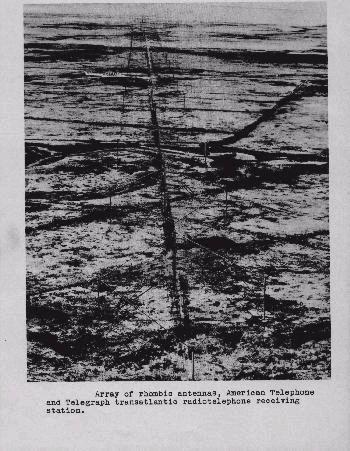 traffic. The Chopmist Hill station had 85,000 feet of wire antenna curtains aloft. The poles were typically 80 feet high and were still aloft in 1968. Not being rotary antennas caused some problems with the strategic listening needs. During the critical Second World War battle of El Alamein in 1942, Cave was calling the Narragansett Electric Company several times daily to reposition antenna poles to optimize reception (truely the "armstrong rotor" method)! On another occasion the rhombics on Chopmist saved the Queen Mary carrying 10,000 American troops overseas by interceptin orders to sink her sent to the U-boat fleet in the Atlantic. The station was also credited to accurately pinpointing the location of every Axis spy within the US by triangulation with other RID stations. Curiously, Frank W3LPL (who had seen the site in the 60's) has told me that the site had a Swastika-shaped fireplace, I suspect as a reminder of their mission, although I am not certain of this. This site was later proposed as the potential site for the United Nations but was later passed up for New York. traffic. The Chopmist Hill station had 85,000 feet of wire antenna curtains aloft. The poles were typically 80 feet high and were still aloft in 1968. Not being rotary antennas caused some problems with the strategic listening needs. During the critical Second World War battle of El Alamein in 1942, Cave was calling the Narragansett Electric Company several times daily to reposition antenna poles to optimize reception (truely the "armstrong rotor" method)! On another occasion the rhombics on Chopmist saved the Queen Mary carrying 10,000 American troops overseas by interceptin orders to sink her sent to the U-boat fleet in the Atlantic. The station was also credited to accurately pinpointing the location of every Axis spy within the US by triangulation with other RID stations. Curiously, Frank W3LPL (who had seen the site in the 60's) has told me that the site had a Swastika-shaped fireplace, I suspect as a reminder of their mission, although I am not certain of this. This site was later proposed as the potential site for the United Nations but was later passed up for New York.
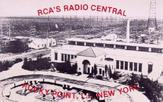
Various commercial rhombic stations exist even today. One is on Cape Cod (Chatham) and is the receiving end of an HF relay link. One of the largest rhombic stations ever was on Long Island at Rocky Point and was an RCA station.
This station was off Route 25A. This station was operational until 1978 and at it's peak had 137 rhombic antennas, many phased together. I have many insulators from this station, including some very distinctive custom-built 4-wire feedline insulators with brass/ceramic turning and termination insulators that were obviously built specifically for the rhombic station. Rhombic termination was accomplished with stainless steel wires strung up the middle of the rhombic. Other commercial stations have used "reentrant" termination, a term I have not yet found a definition for. Evidently reentrant termination permits the station to run unlimited power output without "frying" the termination medium (i.e. melting your stainless steel wire or your resistors)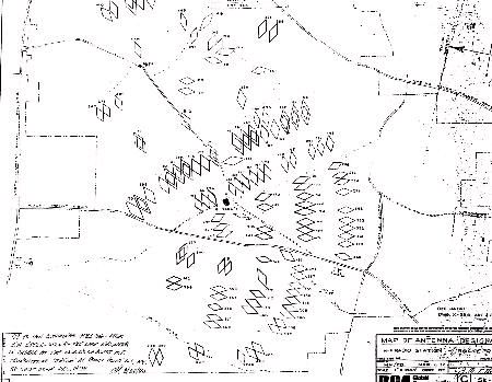
Click here to see the Rocky Point rhombic map with better resolution.
Amateur radio operators still occasionally employ rhombic antennas. In fact, I began my involvement after one day encountering the Don Wallace, W6AM, rhombic station. I at the time was a teenager in Palos Verdes, California. I was riding my bike down a country road and came across a huge installation of rhombics each perched upon telephone poles, some over 150 feet tall! (he used two 75 foot poles spliced butt to butt with redwood and angle iron splices to hold these monster poles together, he also did not like to waste pole length by burying pole in the ground and instead used a metal spike inserted into the bottom of the pole to secure the pole to the ground). The station in 1945 had 120 acres of land (when Don purchased it) with 16 rhombics, the longest being 1500 feet (end to end) and beaming Asia (his favorite antenna). This 1500 foot rhombic is widely believed to have been the largest beam antenna ever in amateur service. He had 61 telephone poles, each at 80 feet and another 90 feed line poles (25 feet high each). These antennas were fed by 52 MILES of feed lines (#8 copperweld). Several of these antennas had 2 or 3 curtains (to smooth impedance and increase gain). In 1962, Don sold 95 acres and consolidated his antennas. He installed ten 140 foot poles on the perimeter of his remaining 25 acres with rhombics layered every 6 feet in various directions with rhombics beginning at the 90 foot level and going in layers of 6 feet up to 140 feet high.
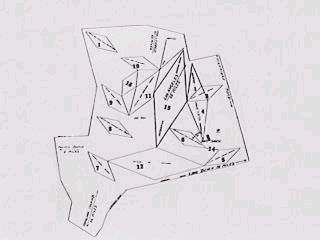
Click here to see the W6AM rhombic farm map image with better resolution.
Click here to read Don's handout he sent anyone inquiring of his rhombic farm
Now his longest (and still favorite) rhombic was 1100 feet end to end. Overall these antennas now covered 16 directions using the 8 rhombics he installed. This was the station I bicycled by. Don showed me his station with the miles of curtains and feedlines stretching for as far as the eye could see and with an operator's desk with a separate Collins station per band. He had his linear amplifier in a cage behind the operator's station and you would tune the amp with a fiberglass rod. The antenna feedlines crossed the ceiling of the station and when you changed directions, you would turn a heavy bakelite know on a rotary switch and the open frame relay matrix would chatter accordingly to your right. In the receiver you would hear various distant stations peak and fall as you electronically swept the horizon faster than any other operators could with their rotary arrays. Additionally, you would hear stations earlier during band openings and often you would communicate easily with far away stations others could not even hear. Nothing short of amazing. Don had an annual "open house" that was well attended. He always would fire up his spark gap transmitter especially for the occasion and demonstrate how a spark station sounded. I also recall Don's KW mobile station in his convertible Cadillac working Russian stations on the 495 Freeway at 60 MPH using an old bug strapped to the seat (on the way to Clifton's in downtown LA for the Southern California DX Association meeting). The code would sound slightly different as we would round steep turns
Eventually, after Don's passing, the station was dismantled for condomiums (Wallace Estates) and there is now a museum station there. At it's closure, the W6AM station had made over 500,000 contacts. I have a few of the W6AM insulators with which to remember this now silent station.
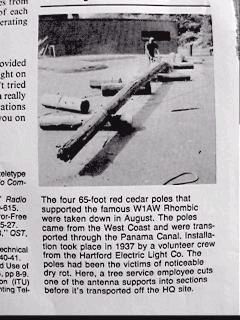
The American Radio Relay League (ARRL) in Newington Conecticut (not far from my home) had a rhombic until 1989, when dry rot in it's cedar support poles forced it to be dismantled (seems to be the fate of most rhombics at some point, they outlive their supports!).
 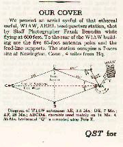 
Click here to see the QST cover rhombic image with better resolution.
Click here to see the QST text description of the ARRL rhombic with better resolution.
Click here to see the image of the dismantling of the ARRL rhombic with better resolution.
This antenna was supported at 65 feet and had leg lengths of 350 feet (theoretical gain of 17dbd on 14 Mhz) with a tilt angle of 70 degrees. It was oriented East-West and is said to have had a stomping signal (loudest in the US as the one wavelength height limited the radiation angle to 15 degrees, about right to be optimum for the 1500 mile hop to the West Coast).
More recently, during the Desert Storm engagement, a group in the Midwest set up a rhombic beaming the Saudi Peninsula to provide point to point communications for the Military Amateur Radio Service (MARS). Again, the rhombic was chosen because of it's excellent point to point communications ability. This rhombic was up around 100 feet high with leg lengths of 294 feet (theoretic gain 15 dbd) and a tilt angle of 70 degrees. This antenna was said to permit eavesdropping on "manpack" tranceivers on the ground with rudimentary whip antennas (I don't doubt this).
Lastly, my modest rhombics. I have a "baby" rhombic that is 377 feet long (end to end) with leg lengths of 210 feet beaming East-West. The tilt angle is 64 degrees and because it is only 40 feet high ("on the ground" in rhombic terms), the radiation angle is around 25 to 30 degrees (very loud to the West coasts of the United States and Africa to say the least!). I also have a rhombic on an unoccupied property that is a bit bigger: 288 feet leg length, 520 feet end to end with a tilt angle of 65 degrees. It is also a bit low at 45 feet (tree supports). Someday I aspire to install a few 90 foot telephone poles but am still trying to figure out an economical way of getting/installing same (any help from out there in internet land?).
As time permits I will be scanning some rhombic-related images in to place here on my page. Some links:
Rhombic Antenna Design Software. This software is included here courtesy of Orrin Winton WN1Z. This program is a windows app and allows you to optimize rhombics for desired wave angles and gain.
Visit Joby Wieser's Rhombic Ranch. Joby has a number of rhombic antennas running
Accumulated email related to rhombics and rhombic history
Plans for VHF and UHF Laporte rhombics
Read the original foreword of Harper's Rhombic Antenna Design textbook
Click here to read Harper's discussion of phasing pairs of rhombics
Click here to read Harper's discussion of lightning supression for rhombic antennas.
View the antenna patterns of various rhombic designs at various frequencies. I think these patterns bring a bit more clarity to how truely great the rhombic antenna really is.American Radio Relay League (ARRL)The League is an organization comprised of radio amateurs with diverse interests. They publish QST magazine.
|