Rhombic Pairs and Multiple Wire Curtains: Harpers "Improved operation may be obtained by means of modified types of construction such as multiple wire antennas and twin antennas. Multiple wire antennas such as shown on Figure 43 and described in more detail in Section 15A, were initially suggested to minimize impedance variations with frequency, and to secure a low and uniform 600 ohm antenna terminal impedance to match an open wire trasmission line without the necessity of a coupling transducer. Twin antennas consist of two identical rhombic antennas in broadside array. The members of a pair need not be separated more than a few feet between adjacent corners and in fact a common pole is generally used to support the midpoint of the system. The twins may be connected to the apparatus by means of two independent transmission lines of the same electrical length, which are multiplied within the building, thereby permitting the independent use of the antennas in emergencies. It has been reported that three wire single rhombic antennas not only have desirable impedance properties, but also may have higher signal gains and freedom from precipitation static when used for receiving. Comparative tests under ordinary operating conditions on a three wire rhombic and an adjacent wimilar single wire rhombic, seem to show signal gains of 1.5 db at 19 mc and 0.7 db gain at 9 mc, in favor of the multiple wire antenna. This apparent improvement is probably due to a lower propogation constant along the antenna conductors, arising from a lower resistance and more uniformly distributed capacity. Similar direct comparisons between the signal-to-noise ration obtained with single and multiple wire rhombic antennas showed that during periods of precipitation static a mean reduction in noise of 9db was apparently obtained on the muliple wire type. Although precipitation static occurs during only a small percentage of the total operating time, in most localities the small added expense of this type of construction may be worth while. Two rhombic transmitting antennas have been fed in parallel to obtain an increase in signal gain of approximately 3 db. Comparative tests between one and a combination of both members of such an identical pair of rhombic antennas for receiving showed improvements of the order of 2 db in signal-to-noise ration." I have also run across a discussion of pairs of rhombics by A. Birrell entitled "The Olifantsfontein and Derdepoort Radio Stations of the Departments of Posts and Telegraphs in the Transactions of the South African Institute of Electrical Engineers, June 1958 (don't ask me how I found it, I don't recall). It is a bit dated but still interesting and addresses both phased rhombics as well as optimizing the alignment of lobes (a topic only glossed over elsewhere). I apologize that I haven't scanned in all of the graphics. Here is a snip: "Rhombic Array Design: The determination of the complete radiation pattern of a rhombic aerial at a number of working freqauencies is greatly simplified by the use of stereographic projection charts first proposed by Foster and further developed by Laport. These transparent projection charts used in pairs give the free space radiation pattern for a rhombic aerial for any required value of the acute angle of the rhombus. Each chart of the pair represents the radiation pattern for one leg of the rhombus. The charts are available for side lengths of from 2 to 7 wavelengths which covers most requirements. The relative field strengths of the various lobes in the free space radiation pattern are given in Table II (n.b. this table is a bit cryptic and provides "order of maxima" in decimal values). Assuming a perfectly conducting earth plane the height factor for a single rhombic due to earth reflection is F = sin (H sin delta) where H is the electrical height of the rhombic in degrees and delta is the vertical angle of elevation. The height factor exhibits a series of maxima and zeros which may be plotted as concentric circles on the stereographic charts. For a rhombic aerial of optimum design the acute angle of the rhombus is chosen so that the side lobes are depressed to zero elevation. The height H is then chosen so the first maximum of F occurs at the elevation of the main lobe. It will then be seen that the side lobes are supressed by the zero in F which occurs at zero elevation while the side lobes are supressed by the second zero in F. Such an optimum design results in the cleanest possible radiation pattern. The radiation pattern of this optimum design degenerates rapidly as the operating frequency is varied from optimum. This optimum design is shown on the stereographic charts in Figure 23. The height factor for an array of rhombic aerials is a very much more complex function of the angle of elevation than that of a single rhombic. The computations for a rhombic array are made relatively easy by regarding the geometric centers of each rhombic element, real or image, as an isotropic point source or radiation and determining the space pattern resulting from the energising of the array of isotropic radiators taking into account the amplitude and phase differences in their excitation. The pattern of the array of isotropic sources is then multiplied by the free space pattern for the rhombic element used, to give the radiation pattern for the rhombic array. It is evident that due to the complexity of the pattern of a rhombic array , unwanted minor lobes may be supressed by destructive interference over a wide frequency range by suitable choice of parameters. The two and four element rhombic arrays based upon these principles provide a power gain of approximately 2.5 and 5 db respectively compared to the unit rhombic. What is perhaps more important is the fact that they are capable of covering a frequency range of at least two to one without serious deterioration of the radiation pattern. Aerial Feeders The transmitters are connected to the aerials by balanced twin wire 600 ohm lines of 300-lb per mile copper wire with a center to center spacing of 10.25 inch. The wires are supported on pedestal insulators without metal fittings at the wire support point and all bends are taken in the vertical plane to maintain equal conductor lengths. Such twin wire lines have low losses, are economical and are quite adequate for the 40 kw peak power output. Aerial Matching The output impedance of a stacked pair of rhombics is approximately 300 ohms and this must be matched over the operating frequency range to the 600 ohm feeder. The interlaced rhombic array requires three 300 to 600 ohm matching sections. 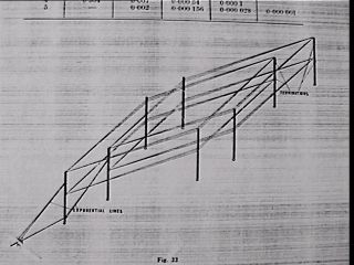 The wideband impedance matching properties of exponential lines are well known and were analysed by Burrows. Christiansen proposed a more practical form of exponential line which does not require closely controlled dimensional changes in spacing and wire diameter. This is a four wire line using a constant conductor diameter. The vertically separated conductors are connected and if: vertical spacing is b, horizontal spacing is d, wire radius is r; the characteristic impedance Z(o) is given by The wideband impedance matching properties of exponential lines are well known and were analysed by Burrows. Christiansen proposed a more practical form of exponential line which does not require closely controlled dimensional changes in spacing and wire diameter. This is a four wire line using a constant conductor diameter. The vertically separated conductors are connected and if: vertical spacing is b, horizontal spacing is d, wire radius is r; the characteristic impedance Z(o) is given by
Z(o) = 138 logd [sqroot (d squared + b squared) divided by br] IF the dimensions b and d are adjusted to correspond to 600 and 300 ohms at the ends and to the geometric mean of 424 ohms at the center of the four wire line, the departure from the characteristics of the ideal exponential line are negligible. The calculated and measured performance of a four wire exponential line is shown in figure 24. Provided the designed cut-off frequency of the matching section which has highpass filter characteristics is sufficiently low, impedance variations in the operating range are not serious. The cut-off frequency decreases with increase in length of the four wire line. The exponential matching sections are connected between the mid point of the stacked rhombics and the feeder at an angle to the horizontal, with a flying spreader at the 424 ohm point in the line. This arrangement is shown in figure 22. The impedance measured at the 600 ohm feeder input of a four element rhombic array is shown in figure 25. 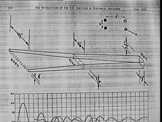 Aerial Construction: Aerial Construction:
The aerials are supported on lattice wood masts which has a constant cross section of 24 by 24 inches. These masts can be assembled in multiples of 9ft 6in to any required height up to about 200 ft. The masts are assembled on the ground by semi-skilled labor and are erected by the falling derrick method. The mastas are adequately stayed and the stays are broken up by insulators which are made off in the stays by means of aluminum alloy ferrules swaged under about 60 ton pressure. THe masts are fabricated in the departmental workshops from selected South African Pine which is pressure creostoted after fabrication. The maintenance of such masts in the Transvaal is negligible over a 25 year period. Rhombic Termination Load A considerable amount of power must be dissipated in the terminating resistance of the rhombic aerial. Christiansen gives the follwing measured value for the fractional power dissipated (table with values from 18-27 percent for 4 wire array, 17-31 percent for 2 wire and 32 to 41 percent for unit rhombic, all depending upon frequency selected). Dissipation Lines: It has long been the practice to use high dissipation stainless steel wire transmission lines for rhombic termination. Until recently, a four wire 300 ohm line of 16 guage stainless steel wire was used to terminate each 300 ohm stacked pair of rhombics. The line attenuation is about 2.5 db per 100 ft at 15 mcs and the line length of 800 ft is adequate. The wire used is a stainless steel which has good magnetic properties and has teh following composition: carbon 0.20%/nickel 1.7%/chromium 16%/iron (balance). Delay Line Absorbers: Recently in order to simplify the aerial terminations, dissipation lines of compact dimensions, in the form of a delay line, were developed. The delay line is a co-axial form and consists of a continuous helical winding of 16 guage stainless steel wire having a winding pitch of eight turns per inch wound on threaded ceramic formers assembled on an inner copper tube. This assembly is coaxially l ocated in an outer copper tube. The characteritic impedance of a delay line is given approximately by: Z9o) = sqroot (L/C) where L and C are the inductance and capacitance per unit length. Once the helix pitch and diameter which determine L and have been chosen, Z(o) may be adjusted to the required value by the choice of the diameter of the outer tube which controls C. In the final design, the helix length is 5 ft and the copper tubes are i in outer diameter and 2.25 in inner diameter. This provides an impedance of nominally 325 ohms with negligible reactance when correctly terminated. The assembly of such a delay and its impedance frequency characteristics are shown in figure 26. The delay line attenuation varies between about 6 and 16 db from 5 to 25 mcs. The terminating resistances are rated at 300 watts and the load is capable of dissipating at least 1.2 kw continuously at any frequency. The dissipation is limited by the terminating resistance at low frequencies and by temperature rise in the delay line due to the rising attenuation of high frequencies. A pair of delay line loads provides a balanced 650 ohm load for each rhombic element. The loads are fitted on the masts at the element termination. From Table III the following continuous ratings are obtained assuming a maximum dissipation of 1.2 Kw per delay line element (table values: two element: 15-28 kw from 8-18 mcs and four element: 35-73 kw from 8-18 mcs). Only at low frequencies is a two element array incapable of absorbing the maximum continuous power output of 20 kw of the high power transmitters. However on ISB telephony transmission where the average power is very low the two element array may be safely operated at peak powers of 40 kw. The introduction of the delay line terminations has resulted in considerable simplification of the constructino of multielement rhombic arrays. Any additional information on feeding pairs of rhombic or other larger arrays of rhombics would be of interest.
|