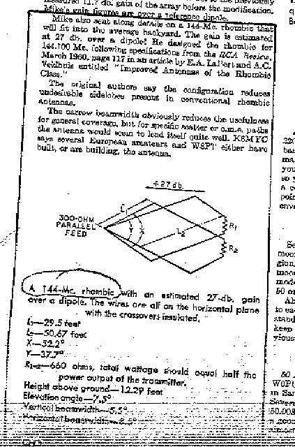
VHF and UHF Rhombic Antennas As I discussed in my main page, modeling rhombics becomes easier at higher frequencies where the mammoth size of high gain arrays becomes somewhat easier. The main problem then becomes impedance matching and mechanical construction, neither of which is real hard. Thanks to Dayton Johnson, W0OZI of Medina Minnesota for his Dual Rhomboid UHF rhombic design that I have reproduced with his permission. This rhombic was featured in a 1996 QST VHF section where there is a picture of W0OZI and his 27dbd antenna. This antenna was constructed from details published in 73 Magazine (July 1977 p. 24, anyone have a copy that they could send me??). Another term I have heard used to describe this design is Dual Hexamerous Rhomboid or DHR for short (Wayne Sarosi, KB4YLY has designed one but I haven't seen his plans yet). Dayton's design recommends booms from clear fir trim lumber that has been painted. He used #12 enameled wire, five plexiglass insulators with 6-32 bolt/nut terminators at the ends. The terminations are 800 ohm noninductive resistors (he uses 4 - 3300 ohm 2 watt resistors in parallel which handles 70W on 440 (ATV) just fine as in this design each resistor handles 1/4 of the power (where most single terminations handle half the power). The balun is made of a section of 3/8 inch hobby tubing that has been split to provide a quarter wave section with enough cut to permit connection to the antenna input bolts at the insulator. He recommends a dremel tool cut off wheel in a drill press to do his cutting. I wonder if a hacksaw and copper tubing is too crude. To complete the balun, a shorter section of the next size larger brass hobby tube needs to be installed over the slotted section to provide a short sliding tuning segment that makes a DC short as it slides up and down the smaller tubing section. A length of flexible coax (9913 or similar but with the stranded center conductor), strip off the outer braid and replace it with the brass tube balun assembly. The center conductor is connected to one side of the slotted balun and antenna input, while the other side of the balun goes to the other antenna input. Dayton describes this as a hybrid of the old conventional half wave line section Bazooka balun and says it works great in UHF applications. A modification if you can't find brass tubing might be to use copper tubing for the first layer and then to use copper sheeting for the second (bent around the outside of the tubing). Click here to see Dayton's Dual Rhomboid plans. Kip Omweg, KD6TBE was kind enough to FAX me a copy of an old QST reference for a similar Dual Rhombic that is attributed to K6MYC and to E.A. LaPort and A.C. Veidhuis "Improved Antennas of the Rhombic Class" RCA Review, March 1960, p. 117 ( I am getting a copy for chuckles). Seems this is the source for the Dual Hexamerous Rhombic. This design would seem optimum for my plan to try Aurora communications on 144.2, I will let you know. This design is cut for 144 Mhz and has a length of less than '80 feet for 2 Meter operation (big but manageable). In case you can't read the dimensions, here they are: L1- 29.5 ft, L2- 50.67 ft, X- 52.2 degrees, Y- 37.7 degrees, R1/2 660 ohms noninductive, Ht: 12.29 ft, Elevation angle: 7.5 degrees, Vertical beamwidth: 5.5 degrees and Horizontal beamwidth: 8.5 degrees. Total gain: 27 db. Click here to see the QST snip related to the 144 Mhz Dual Rhomboid Antenna.. I hope you found this to be useful!
|