Design Parameters There are two manners in which rhombic dimensions are determined. The first method results in a rhombic with the maximum output possible in a given azimuth direction. No constraints are placed upon the wave angle (elevation plane). 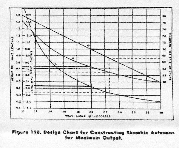 In order to use the maximum output chart, simply choose the single variable you know: height, leg length, tilt angle or wave angle (elevation plane). If you choose the wave angle, you then draw a vertical line as seen in the example chart. This line intersects the three curves (L for leg length, H for height and theta for tilt angle). Where each is intersected draw a horizontal line from each curve to find the resulting value. This lets you calculate the maximum output for those parameters. The so-called compromise rhombic allows the designer to depart from maximum output characteristics and make calculated compromises for the given parameters they are presented with by practical circumstances. 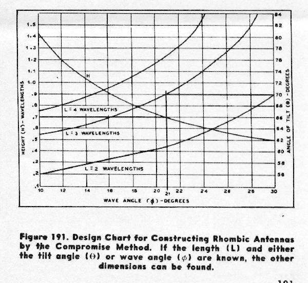 Example: to get maximum output at 14 degree elevation, the maximum output graph tells you that you will need 8 wavelength legs with a tilt angle of about 76 degrees at one wave above the ground. That may not be entirely practical. The compromise table tells you that you can do almost as well with about 4 wavelength legs also at one wave above ground with a tilt angle of around 70 degrees. Practical Aspects: poles, curtain and termination The construction of the actual curtain has many technical details. The poles must be stepped appropriately (so much in the earth for a given height of pole above ground).The curtain is usually three conductors each spaced about 6 feet apart at the sides converging to the feed and termination points at each end. The feedline is exponential to bring the 600 to 800 ohm rhombic feed down to 200 or so ohms. 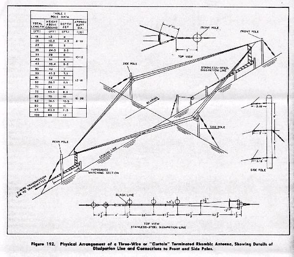 The termination is a stainless steel (Nicrome) wire that tapers to a ground rod to provide a DC ground for lightning protection. The stainless steel provides the noninductive resistive load for termination with sufficient power dissipation to be useful. Additional attention must be paid to the wire sag, distance from poles (3 feet usually on sides and 8 inches on ends). The Figure below has also the dimensions that work well for given circuit distances (200 to 400, 400-600, 600-1000, 1500-2000, 2000-3000 and 3000+ miles) based upon the compromise tilt angles, leg lengths, heights above ground and leg lengths. 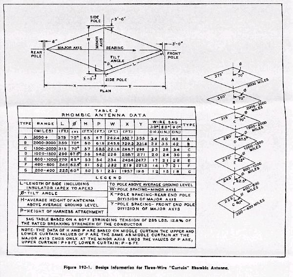 These dimensions make good starting places for the would-be rhombic builder. The various distances given are simply a manifestation of the radiation elevation angle typical of each of the rhombic designs. Work them out on the graphs and you will see that the "3,000_" rhombic has a radiation angle of around 16 degrees or so (about right for signals arriving from over 3,000 miles). The figures allow you to deal with curtain spacing for three wire rhombics as well as with sagging of each curtain span. These details also appear in the World War II rhombic manual. These figures come from a more recent Military publication but are virtually identical to those found in the World War II manual. Termination and Dissipation 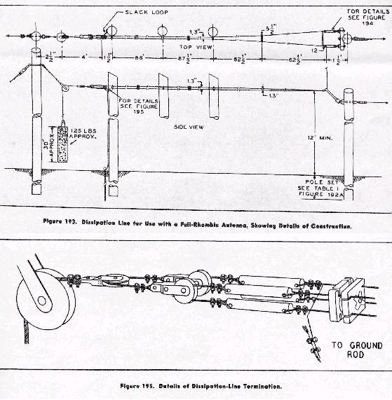 The dissipation line is basically a way to terminate the rhombic at higher powers. The figure demonstrates not only how to construct the dissipation line but also how to counterweight it to obtain correct tension and the grounding rod (dissipates static). Note that there is a 62' 6" section of tapered line that leads from the feeder to the dissipation line to provide impedance matching. 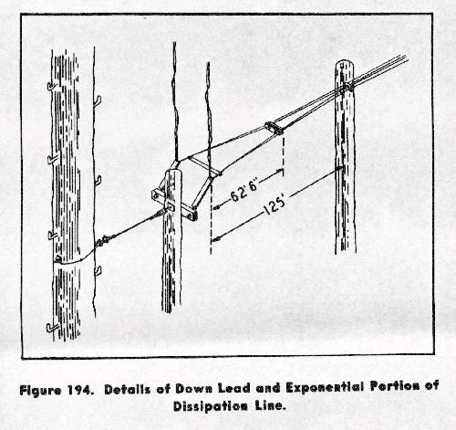 The last figure shows the exponential feeders, used to match the 200 ohm or so feedline from the radio room to the 600-800 ohm rhombic feedpoint. It's basically the poor man's broadbanded transformer. As the figure implies, there is an exponential feedline at the feed end and also at the termination end. The exponential feedline allows the appropriate impedance across the entire useful frequency range of the rhombic 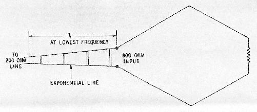
|